Reassembly
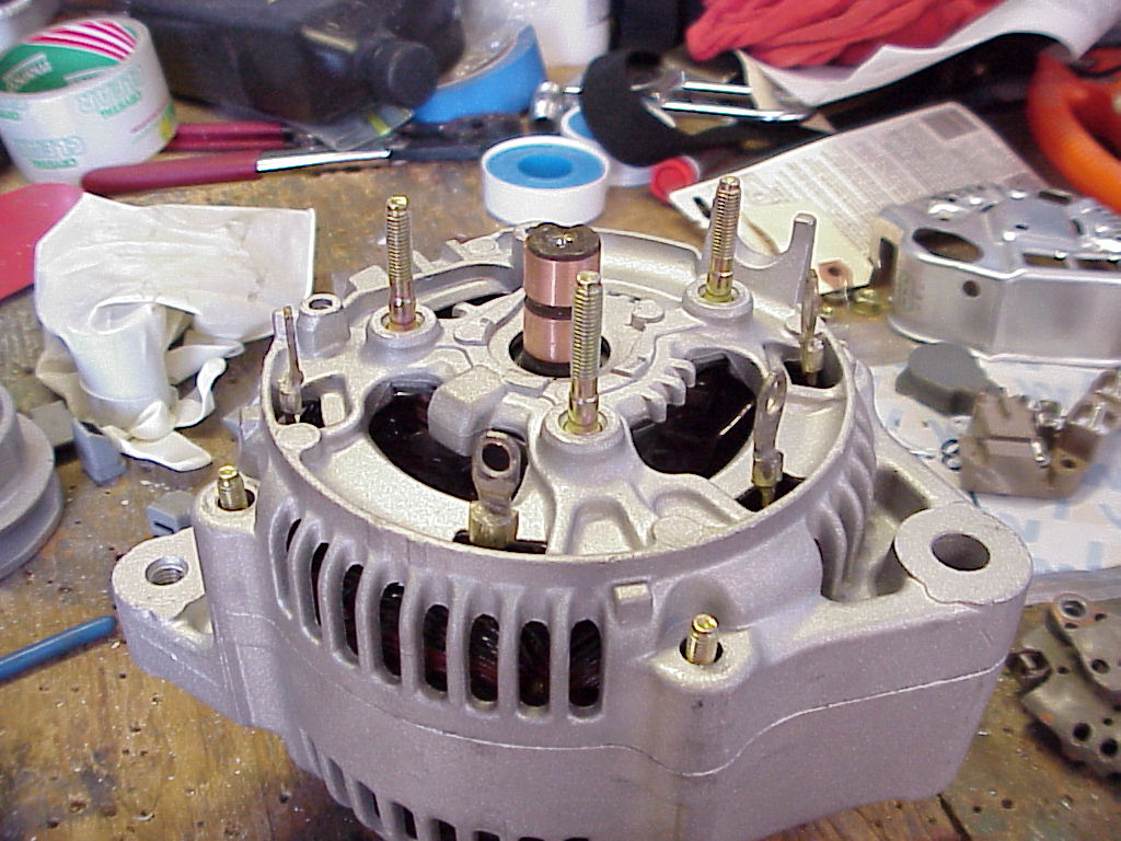
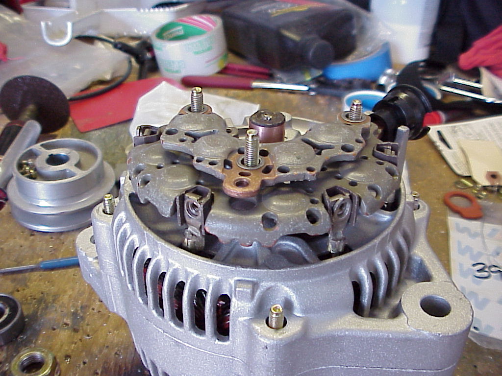
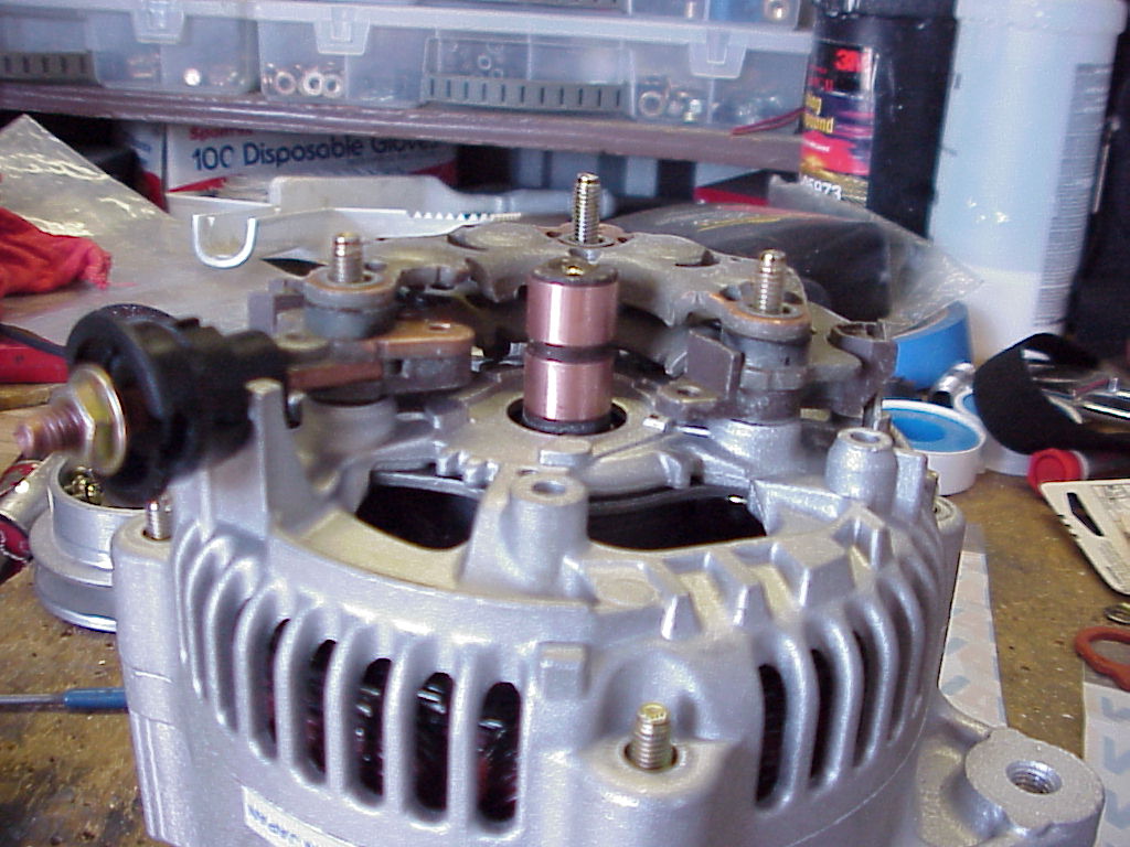
The next 3 images show the unit going back together, and as you have probably
noticed I forgot to put all the rubber boots on.
So take it all apart and do it all again if you are like me, and need the
practice.
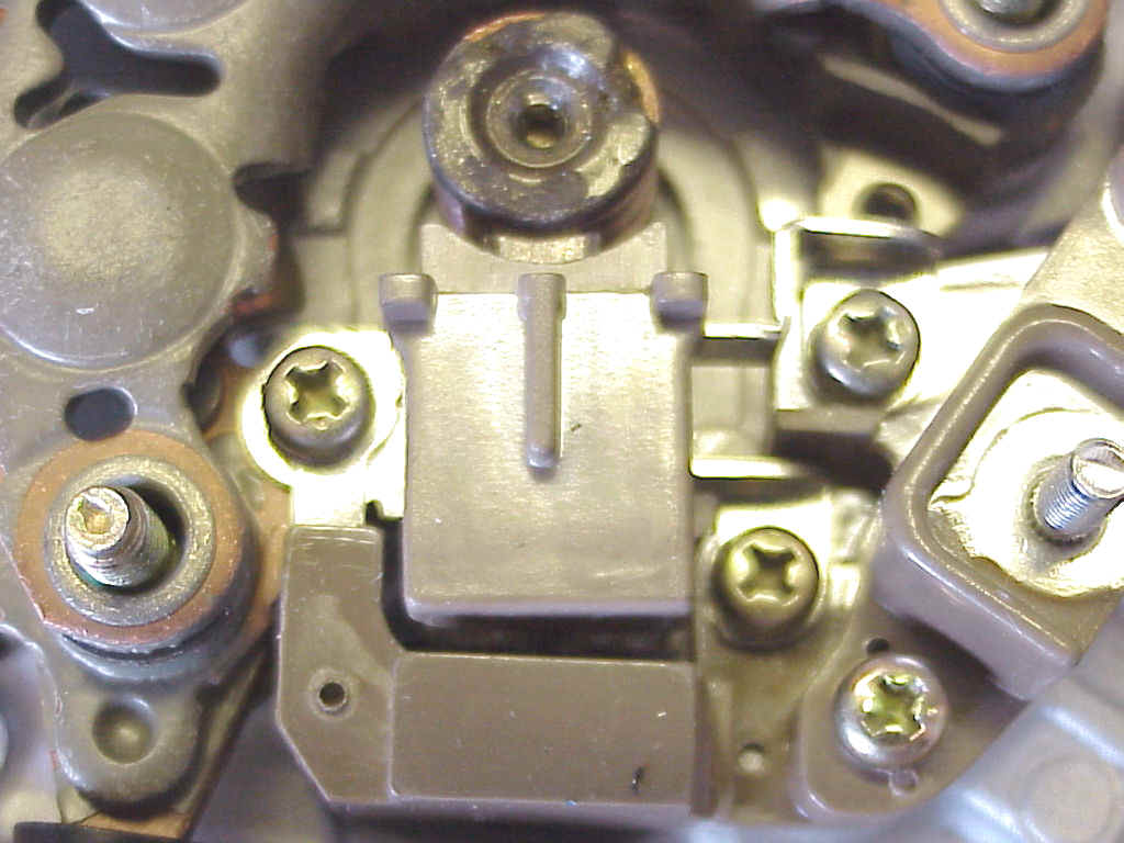
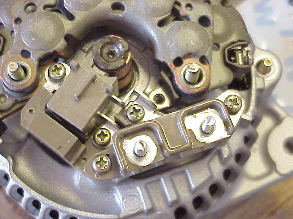
The two images below show the new brushes and terminal blocks going in place, and,
once again you have probably noticed that I forgot to install the lower brush
red boot.
Also note the overlap of the left brush screw.
This tang for the brush does nothing but hold it in place in spite of the fact
that this lug on the rectifier is part of the positive lug.
The left most tang on the terminal block that overlaps this goes to one side of
a noise filter cap in the terminal block. It needs to be on top of the brush
assembly lug for the brush assembly to sit square to the slip rings. It will
cause the left part of the terminal mount to look slightly askew, but this is
just the section that has the filter cap in it.
The other two lugs on the right side of the brush assm. go to the two terminals.
One terminal lug goes to ground and the other comes from the external regulator once
the unit is assembled and installed.
One way to reduce regulator noise is to use a shielded wire from the reg.
Have the inner conductor go from the reg to one post, and the shield go from the
other post back to the reg area, where its then grounded.
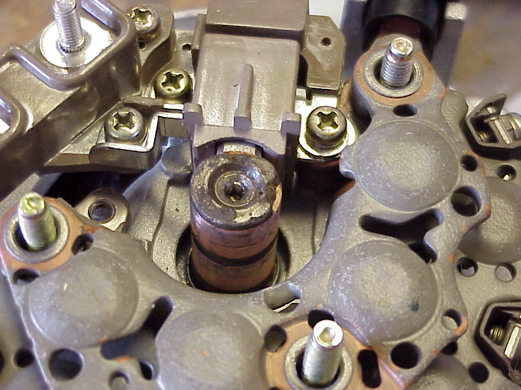
Its important to check that the brushes are well aligned and squared to the slip
rings.
If they ride slightly high or low this is OK as long as they make full contact.
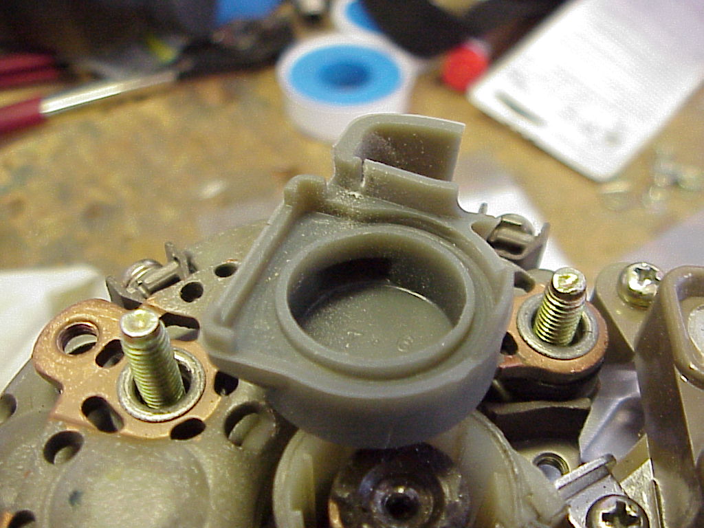
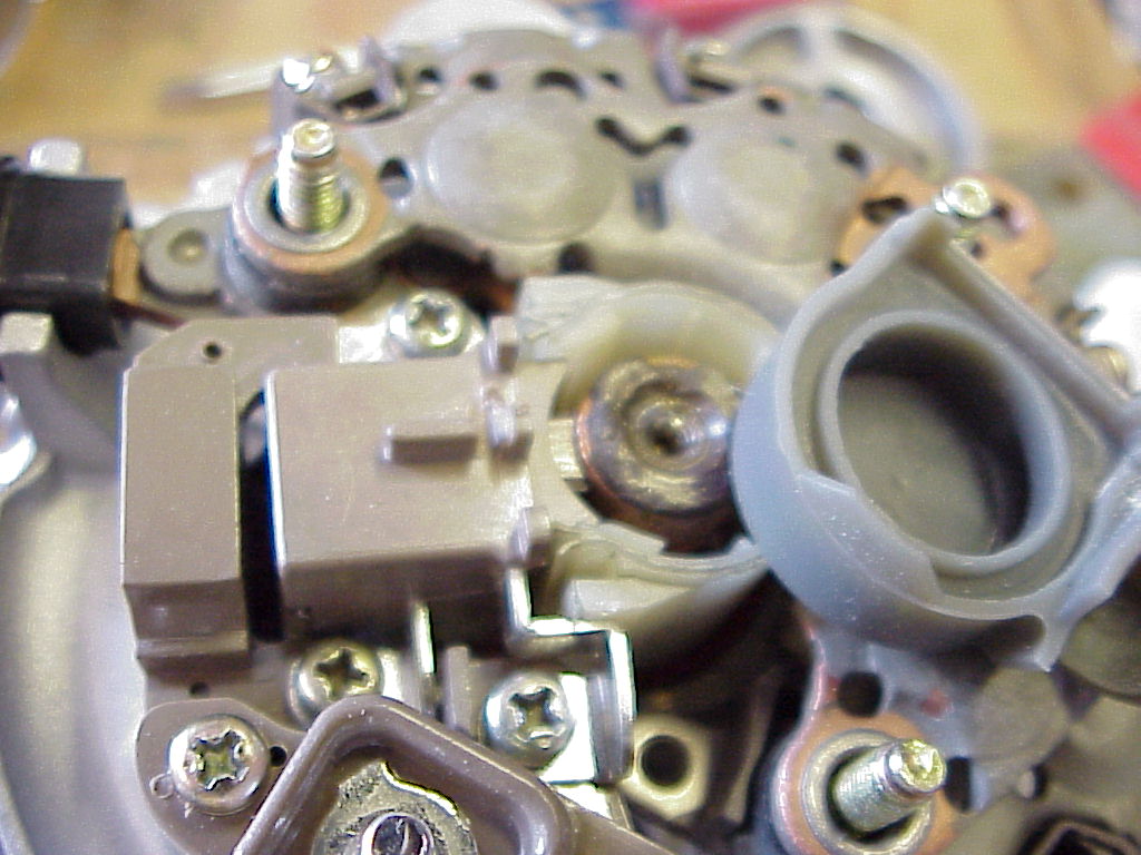
These next few shots show some slight trimming (slots) I had to do to the aft
rubber boot and the new brush assm. to make the boot fit cleanly.
Note in the right picture the white plastic brush cover half cylinder. This is
held in by being trapped between the alt. rear case and rear cover.
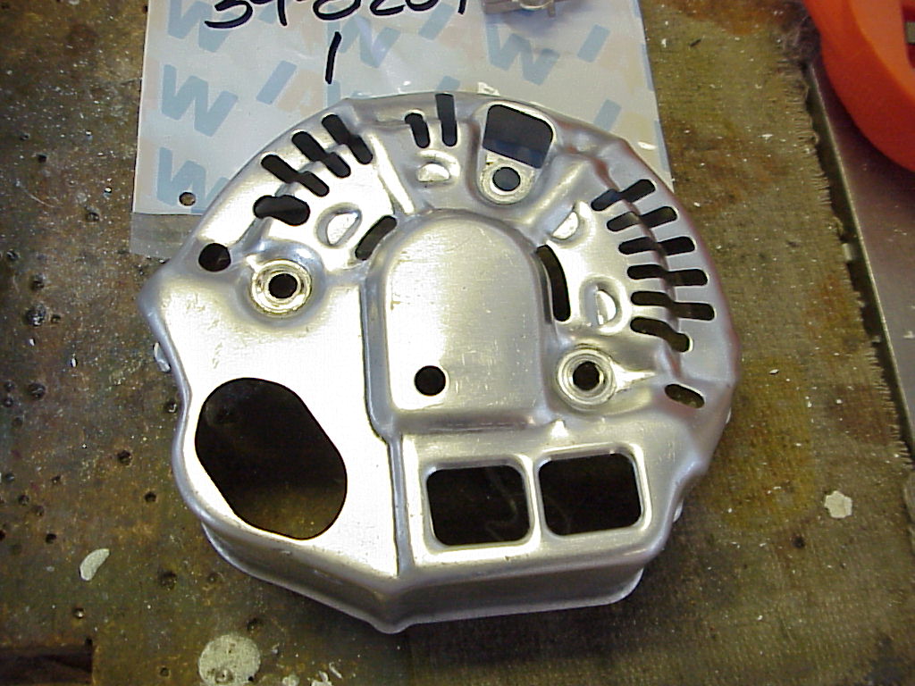
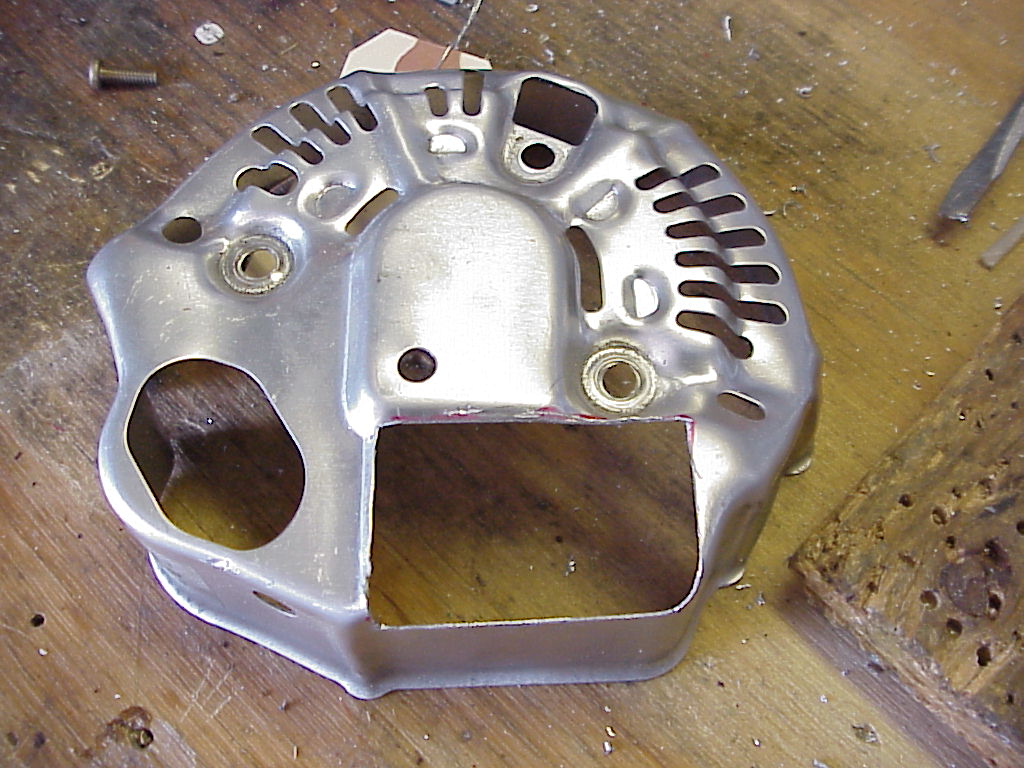
This shows the rear cover modified to fit the terminal block.
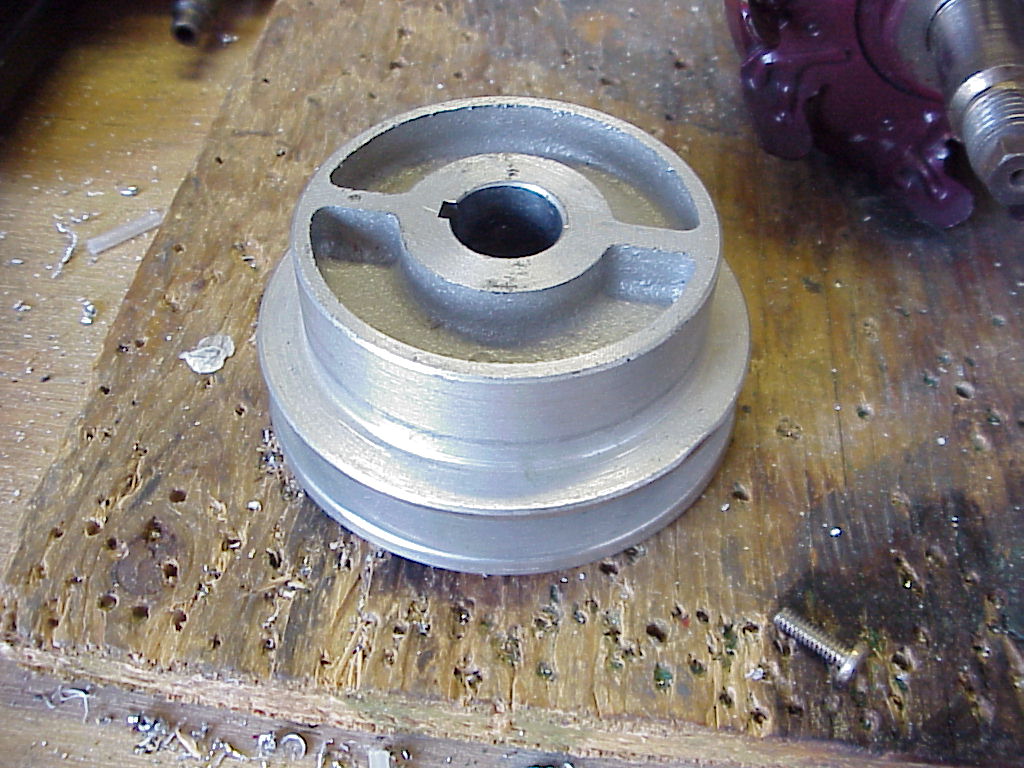
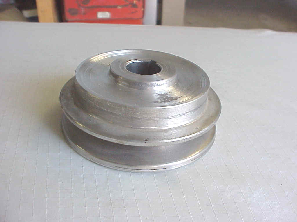
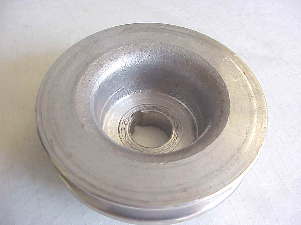
The following images and drawing show the Prestolite pulley as new and as modified. The aft side has a
collar and web that needs to be removed, then the aft stepped boss needs to have
about 5mm removed from it.
Inside the front of the pulley there is also a boss step that needs to be cut
flush. This should leave about 10mm of depth in the pulley mount boss to
correctly position the rotor and leave enough room for the nut to engage. Make
sure you leave enough of the aft boss so that the rear face of the pulley
doesn't rub the front alternator case. Use the original pulley as a guide.
The key is not needed. In fact all new alternators don't seem to use keys
anymore.
Use a strap wrench and torque wrench to tighten. I went for 30ft/lbs. I also put
some torque seal on this for inspection purposes.
These two show the steel Lycoming boss mount with the new bolt and the two shims.
These are 1" diameter and 0.135" for the front, 0.475" for the
rear, with a 3/8" bore.
The rear one needed to have a corner shaved a bit as the mount is angled there.
These shims can be different if you have a different boss mount. Its important
that the pulleys line up as closely as possible so be careful with these
measurements..
The main bolt is 4.5" x 3/8" NC and the adjust arm is a 8mm x 1.25 x
40mm.
This latter length leaves enough room out the back to lock nut the adjustment
fastener.
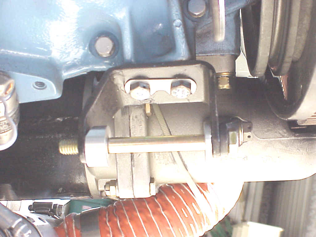
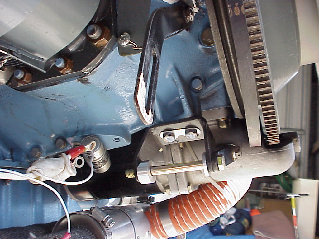
These last few show the new alternator installed. I was able to use the same
belt and swing arm, but the slot on the arm needed to be extended 1/8" upwards.
If I had wanted there was plenty of room in the cowl to install the next longer
belt.
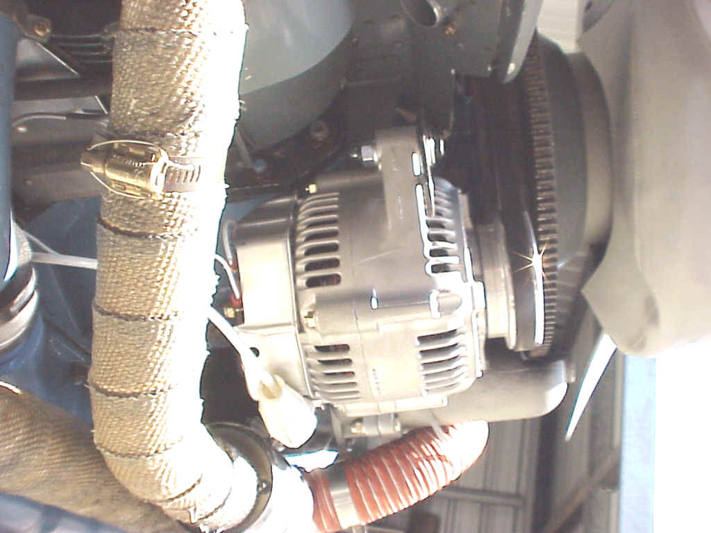
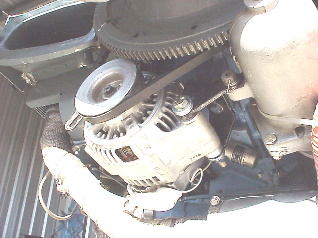
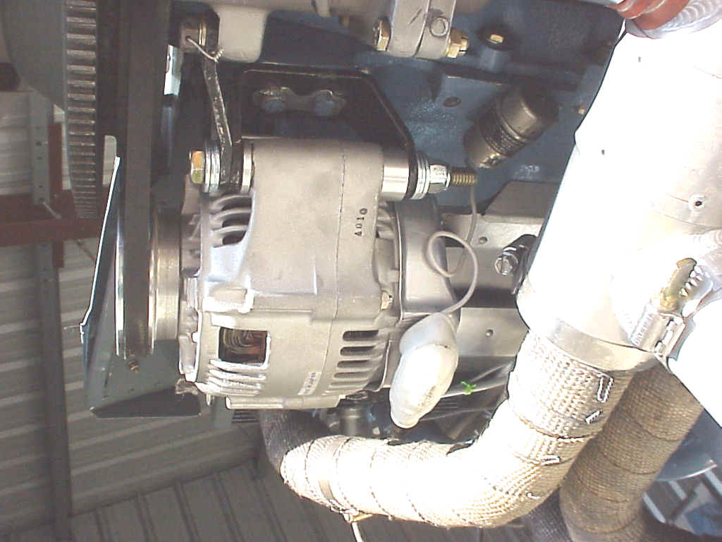
The currently installed main bolt is a 5" and is somewhat long, but the
4" didn't have the grip make it all the way through the alternator and the
mounts. It seems a 4.5" x 3/8" grade 8 will take a special order to
locate.
Its also very important that the tang that goes from the forward mount over to the starter be installed. This is true for any of the boss mounts.
As stated above this alternator has a greater rating than the typical conversion units do. Toyota rates it at 90 amps intermittent duty. As soon as we get caught up I will provide some more data on how well it does during continuous duty tests. You might wonder why I want 90 amps, well I don't, but I would like 60 amps continuous if I need it.
With the Prestolite I was getting a bare 35 amps, which was my load when all is on and xmitting. It is a 36 year old unit that was structurally marginal due to case wear. And these are getting hard to find parts for these days. The new unit has parts that are current standard parts. And finally the new weighs one pound less then the old.
Total cost to me was $300, but I could have reduced that by about $80 if I had the time to find a good unit in a recycle yard.
Any questions wnorth@sdccd.net